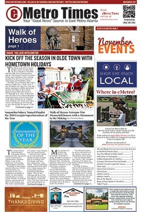
Most
all of these tech tips or tech articles I stoll, so I just see this as a central
portal to super tuning your Polaris.
Tip #1 buy a Polaris, Ski Doo = slow (Live it - Learn it...)
Choose
your Topic:
The Holeshot
Pilot Air Screws
Gearing your sled
TPS Adjustment
Carb Boot Mod
Establishing a Jetting Baseline
Airbox Temperatures
Pipe Temp and Airbox Pumping
Torque or Horsepower?
INSIDE Suspension Coupling!
CHOOSING AN OIL!
NGK Spark Plugs
| Getting off the starting line is crucial to winning in many forms of racing, from drag racing your buddies to sno-cross. There are some basics that can help. Traction, suspension, clutching and gear ratios will be the focus of this article. Of course it is also important to have a torque-filled powerful engine, but we are going to concentrate on tuning the sled to utilize the power you already have. The way you obtain good traction
for your holeshot is dependent on the surface on which you are riding.
For snow, deep lugs are needed. Ice requires sharp studs.
If the ice is soft, a few chisel studs may help. Chisels also work
for dirt or grass. The following recommendations are made under
the assumption that traction has already been maximized. Weight transfer is a critical
factor. Because the center of gravity of a snowmobile is above the
line of force, the point where the track grips the snow, ice or ground,
the front of the machine rises upward when you accelerate. The rear
suspension should be set to capitalize on this principle of physics.
Two things should happen: The rear springs should compress and the center
spring, front of the rear suspension, should extend. The result
should be a transfer of weight to the rear of the sled which pushes down
on the track. If the front end of the sled comes up too high a couple
of bad things happen. First, you have wasted energy by going up
with the front of the machine instead of forward. Secondly, the
front portion of the track will not grip the surface well. On the
other hand, if the front end does not come up at all, then weight
has not been transferred. This means that the skis are dragging
and the track does not grip as well because there isn't as much weight
on it. If the rear suspension is set correctly, the skis should
come up a few inches and the track should be flat on the riding surface. This is accomplished by extending
the limiter straps, increasing the preload of the spring of the front
of the rear suspension and softening the rear springs. There is
no free lunch here, however. These adjustments have a negative effect
on your sled's ability to corner. The inside ski will lift
more readily. If you are out drag racing with your buddies, soften
the rear springs (softest cam setting or lighter springs) and let out
the limiter straps enough so the skis come off the surface a few inches.
Now set the preload on the center spring, front of rear suspension, very
stiff. This will give the track good bite. On the other hand,
if you are riding the twisties through the woods, start sucking up
the limiter straps until your sled corners to your liking. A middle
ground setting would be to keep the rear springs fairly soft, shorten
the limiters until you can live with the corners and keep a high preload
on the center spring. Let's take a look at clutching.
The objective for clutching a snowmobile for a good hole shot is
to utilize as much of the engine's available torque as possible without
spinning the track. Once the track breaks loose, traction is lost.
There is a lesson to be learned from driving a car on ice. To get
started it is beneficial to start out in second gear. When we do
this we have limited the engine's torque to match the available traction.
This is also true for snowmobiles. Most sleds have ample torque to spin
the track on take off on almost any surface. We need to limit it,
especially just as the sled begins to move. This can be done in
a number of ways. The easiest is to adjust your drive belt lower
in the secondary, which is like starting out in second gear. Torque
is force times distance, and putting the belt closer to the jackshaft
reduces the distance, thereby reducing the torque. This also
means the primary clutch will slip more before it grabs the belt.
Belts won't last as long. Another method is to install
a different helix that will allow the clutches to shift to a higher ratio
very rapidly at the beginning of the launch, but then slow down the upshift
shortly thereafter. This is done with a multi-angle helix.
A rule of thumb here is to have the first number about ten more than the
stock straight-angle helix and the second number about two less.
Fine tuning can be done with the belt position and spring tension in the
secondary. For example, if the engine bogs, the belt can be
raised in the secondary and/or the spring tension can be increased.
On the other hand, if the track still spins too readily, the belt
can be lowered in the secondary. You probably don't want to reduce
spring tension because that will affect your backshift. If the shift-out
R.P.M. are changed this should be adjusted with changes in the primary
clutch. It can be done by changing springs: lighter to lower R.P.M.
or heavier to raise them. You can also add or subtract weight to
the lever arms or fly weights. Changing sprockets can also
be considered. A larger top sprocket will reduce torque. This
change will effect the entire pattern from low end to top end. It
will help limit track spin but probably will also reduce acceleration.
It may, however, increase top end. Speed-run people like big-top
sprockets. These are some basics for tuning for a good holeshot. Hopefully, they will be helpful as you attempt to fine tune your sled to meet your riding needs. Good luck. |
Many Polaris XC's owners are frequently annoyed by a high idle. Many dealers recommend turning out the fuel screws to richen the idle mixture, but that just loads up the engine. A much better solution is to install 1.0 PAJs (Pilot Air Jets) in place of the 0.9s that come stock. We found that the 1.0 PAJs helped DE-sensitize the carb idle circuits and made the "high-idle" problem much less bothersome. And yes, I know that some guys went to smaller PAJs and screwed out the fuel screws in an effort to do the same thing... I don't consider flooding the engine with unneeded fuel a solution. The 1.0 PAJs allow you to turn down the idle speed, and idle comfortably without loading up. Replacing the PAJs is very easy to do and doesn't require taking apart the carbs. Just open the top of the airbox and lay it aside. You will see the carb throats, and the PAJs are right there. Use a small screwdriver and DON'T DROP them in the engine!
The correct Polaris part number for the long 1.0 PAJs is 3131257.

Formula
to calculate MPH:
RPM / GR x SC / 12 x 60 / 5280 = MPH @ 1:1 clutch ratio
GR = gear ratio (divide top sprocket into bottom sprocket)
SC = sprocket circumference
7T - 2.52" Pitch = 17.64 SC
8T - 2.52" Pitch = 20.16 SC
9T - 2.52" Pitch (std. OEM size) = 22.68 SC
10T - 2.52" Pitch = 25.2 SC
7T Convolute - 3.29" Pitch = 23.03 SC
Formula to calculate chain:
(CD x 2)/.375 +(TS + BS)/2 = Pitch
CD = center distance (drive shaft to Jackshaft)
TS = top sprocket
BS = bottom sprocket
--Round number up to even number for proper pitch
600
& 800 gearing recomendation chart. The column at the far right has chain
slack under the "Differ" heading.
Example: Stock 800 edge has 25 tooth upper 40 tooth bottom and
76 pitch chain = 1.60 ratio with .187 chain slack.
That chain slack is what makes all that brake noise. So going to a 24/39 gear
set with a 74 pitch chain - 1.63 ratio with .002 chain slack. Brake noise will
be reduced and a straight chain equals better effenciancy. You will need
to grind some material off the backside of the tensioner to fit.
For you 600XC boys go from stock 23/39 gears to 22/37 gears with a 72 pitch chain.
Remember
numerically lowering ratio will increase mph
Example
1.60 ratio at 8000 rpm=107.4 mph.
1.63 ratio at 8000 rpm=105.7 mph
| SNOWMOBILE SPROCKET / CHAIN COMBINATIONS (RED=no good, N/R=Not Recommended, BLUE=can be used safely) | ||||||||||||||||||||
| XCF STANDARD CHAINCASE, 6.625 CENTER DISTANCE | 7.050 CENTER DISTANCE CHAINCASE (97 and later RMK, XC) |
EDGE 7.920 CENTER DISTANCE CHAINCASE | ||||||||||||||||||
|
|
|
|
|
|
|
|
|
|
|
|
| |||||||||
|
|
|
|
|
|
|
|
|
|
|
|
|
|
|
| ||||||
|
|
|
|
|
|
|
|
|
|
|
|
|
|
|
|
| |||||
|
|
|
|
|
|
|
|
|
|
|
|
|
|
|
|
|
|||||
|
|
|
|
|
|
|
N/R |
|
|
|
|
|
N/R |
|
|
|
|
|
|||
|
|
|
|
|
|
|
|
|
|
|
|
|
|
|
|
|
N/R | ||||
|
|
|
|
|
|
|
|
|
|
|
|
|
|
|
|
|
|||||
|
|
|
|
|
|
|
N/R |
|
|
|
|
|
|
|
|
|
|
||||
|
|
|
|
|
|
|
N/R |
|
|
|
|
|
N/R |
|
|
|
|
|
|||
|
|
|
|
|
|
|
N/R |
|
|
|
|
|
N/R |
|
|
|
|
|
|||
|
|
|
|
|
|
|
|
|
|
|
|
|
|
|
|
|
N/R | ||||
|
|
|
|
|
|
|
|
|
|
|
|
|
|
|
|
|
|||||
|
|
|
|
|
|
|
|
|
|
|
|
|
|
|
|
|
N/R | ||||
|
|
|
|
|
|
|
|
|
|
|
|
|
|
|
|
|
|||||
|
|
|
|
|
|
|
N/R |
|
|
|
|
|
N/R |
|
|
|
|
|
|||
|
|
|
|
|
|
|
N/R |
|
|
|
|
|
N/R |
|
|
|
|
|
|||
|
|
|
|
|
|
|
|
|
|
|
|
|
|
|
|
|
N/R | ||||
|
|
|
|
|
|
|
|
|
|
|
|
N/R |
|
|
|
|
|
N/R | |||
|
|
|
|
|
|
|
|
|
|
|
|
|
|
|
|
|
N/R | ||||
|
|
|
|
|
|
|
|
|
|
|
|
|
|
|
|
|
|||||
|
|
|
|
|
|
|
N/R |
|
|
|
|
|
N/R |
|
|
|
|
|
|||
|
|
|
|
|
|
|
|
|
|
|
|
N/R |
|
|
|
|
|
||||
|
|
|
|
|
|
|
|
|
|
|
|
|
|
|
|
|
|||||
|
|
|
|
|
|
|
|
|
|
|
|
|
|
|
|
|
N/R | ||||
|
|
|
|
|
|
|
|
|
|
|
|
N/R |
|
|
|
|
|
N/R | |||
|
|
|
|
|
|
|
N/R |
|
|
|
|
|
N/R |
|
|
|
|
|
|||
|
|
|
|
|
|
|
N/R |
|
|
|
|
|
N/R |
|
|
|
|
|
|||
|
|
|
|
|
|
|
|
|
|
|
|
|
|
|
|
|
N/R | ||||
|
|
|
|
|
|
|
|
|
|
|
|
N/R |
|
|
|
|
|
N/R | |||
|
|
|
|
|
|
|
N/R |
|
|
|
|
|
N/R |
|
|
|
|
|
|||
|
|
|
|
|
|
|
N/R |
|
|
|
|
|
|
|
|
|
|
||||
|
|
|
|
|
|
|
|
|
|
|
|
|
|
|
|
|
|||||
|
|
|
|
|
|
|
|
|
|
|
|
N/R |
|
|
|
|
|
||||
|
|
|
|
|
|
|
N/R |
|
|
|
|
|
N/R |
|
|
|
|
|
|||
|
|
|
|
|
|
|
N/R |
|
|
|
|
|
|
|
|
|
|
||||
|
|
|
|
|
|
|
|
|
|
|
|
|
|
|
|
|
|||||
|
|
|
|
|
|
|
|
|
|
|
|
|
|
|
|
|
N/R | ||||
|
|
|
|
|
|
|
N/R |
|
|
|
|
|
N/R |
|
|
|
|
|
|||
|
|
|
|
|
|
|
N/R |
|
|
|
|
|
|
|
|
|
|
||||
|
|
|
|
|
|
|
|
|
|
|
|
|
|
|
|
|
|||||
|
|
|
|
|
|
|
|
|
|
|
|
|
|
|
|
|
N/R | ||||
|
|
|
|
|
|
|
|
|
|
|
|
|
|
|
|
|
N/R | ||||
|
|
|
|
|
|
|
N/R |
|
|
|
|
|
|
|
|
|
|
||||
|
|
|
|
|
|
|
|
|
|
|
|
|
|
|
|
|
|||||
|
|
|
|
|
|
|
|
|
|
|
|
|
|
|
|
|
N/R | ||||
|
|
|
|
|
|
|
N/R |
|
|
|
|
|
N/R |
|
|
|
|
|
|||
|
|
|
|
|
|
|
N/R |
|
|
|
|
|
N/R |
|
|
|
|
|
|||
|
|
|
|
|
|
|
|
|
|
|
|
|
|
|
|
|
N/R | ||||
|
|
|
|
|
|
|
N/R |
|
|
|
|
|
|
|
|
|
|
||||
TPS adjustment
The TPS (Throttle-Position-Sensor) is an important part of the XC setup. It effects how lean you can go in the mid-range especially, because it controls how fast the spark advance curve comes in. There have been a good number of reports coming in about part-throttle detonation, (knock), on all of the XC motors, (and even overheating on the XC600). The detonation is aggravated by leaning the mid-range (lowering the needles), and also by installing heavier clutch weights (puts more load on lower rpms). So you need to consider your overall setup before you make big changes in the jetting. Even if you are not changing your jetting I recommend resetting the TPS sensor. Our 2002 XCs run much better after this adjustment.
Does your XC500 or XC600 have a roughness at 5000rpm? Or does your XC700 or XC800 have a "clatter" at 5000 to 6000rpm? Almost all 2002 XCs have these symptoms, and it is because the factory TPS setting is too high. Readjusting the TPS will make your XC run smoother and safer at low speeds. The best way to adjust the TPS setting is to use the Polaris TPS Tester #2201519. The wire harness and the regulator are included in the kit. The VOM and the 9V battery are not included. You also will need a "tamper proof" T25 Torx bit to adjust the TPS sensor, (or you can drill out the center of a standard T25 bit)..
Important Recomendation: On all XCs with the TPS sensor, (500, 600, 700 & 800), set your TPS voltage (using the Polaris TPS tester or a homemade substitute) to Not More Than 4.0 volts at WOT. Some XCs have come from the factory with much higher TPS voltage settings, and these seem to be the ones reporting part-throttle detonation.
Carb Boot Mod - American Built Twins
| LOW $$$ HORSE POWER FOR XC SP 500-600-700-800'S |
|
What you are doing is removing the reed stuffers , opening up the carb boots to a "v-force DELTA 2"size rectangle , have them checked on a flow bench (IMPORTANT !!! YOU MUST HAVE BOTH BOOTS MATCHED WITHIN 1 CU. FT. OF AIR FLOW!!!).The results are about 4 H.P. increase on a 01/02 600 ! This mod should be the first thing you do to inprove your sleds proformance-works great with stock reeds!Do not open the boot larger than a v-force pattern or they will loose too much strength.
BEFORE
AND AFTER PICS OF CARB BOOTS Any one that does cylinder porting should be able to handle this mod for you....just make sure that they flow bench those suckers and match 'em for you! Also...a boost bottle (SLP PLASTIC BOW-TIE STYLE)really helps clean up the bottom end on these twins.Gets rid of all that fuel spit-back in your air box...but POLARIS left no room on the '03 models for one...still helps on the '01-'02's....forget your drills and razor knife when installing-just use a well oiled 3/4" hole saw for a perfect cut ! |
Establishing a Jetting Baseline
Regardless
of whether your sled is bone stock or you have added some accessories, one of
the most important pieces of information you need for consistent peak performance
is to establish is a “jetting baseline”. This is when you fine-tune and jet
your carburetors for a specific set of conditions. Once you determine a baseline
for your exact intake/engine/exhaust combination, you can use the data to properly
calibrate your jetting for whatever conditions you may ride in. This procedure
is especially valuable for unique combinations that deviate from the factory
supplied jetting charts.
You will of course want to start with the jetting recommendations supplied by
the manufacturer for your exact model. Normally, your sled will be jetted for
conditions colder than what you’re likely riding in to maintain a “safety margin”.
If you have added aftermarket accessories, follow the recommendations supplied
by that vendor. If they do not supply any suggestions, always err on the rich
side.

While more precise tuning can be performed using exhaust gas temperature gauges,
you can perform very accurate tuning by simply analyzing the spark plugs and
the piston wash. Many tuners will simply learn to read spark plugs, as this
is clearly the quickest and easiest method.

At the time of your testing, air temperature and elevation, at a minimum, are
required to determine your baseline specification. Better yet, what you’re really
interested in is Relative Air Density, a reading that is a combination of air
temperature and barometric pressure. You can determine the proper jetting for
your sled at a given temperature and elevation, but if this was performed when
a low pressure air mass was present, you could be too lean at that same elevation
and temperature if a high pressure air mass passes through. A higher barometric
pressure means that the air is denser, and there will be more molecules of oxygen
entering your engine, thus a leaner fuel/air mixture.

An air density guage can bepurchased from most leading performance shops. (Part #725-160 for $129.95 from Hi-Performance Engineering at 218-681-2390 or 1-800-451-5268
Make sure your machine is good and warmed up by running it for a while before
beginning any calibrations. You want to safely operate the machine at wide-open
throttle for at least 1/4 mile on a flat, well packed surface. While at full
throttle, shut off the ignition before releasing the throttle. When the sled
comes safely to a stop, examine the spark plug color, piston domes, and even
the exhaust manifold to determine if the mixture is rich. Because of the differences
in engine designs and hundreds of performance products available for these engines,
you may want to contact a dealer or performance company that is familiar with
your engine combination and talk to them about any specifics you should be aware
of when “reading” your plugs and pistons.
Generally, if the spark plug insulator (white porcelain surrounding the center
firing electrode) is dark brown or black, the mixture is too rich. Hopefully
you are familiar with the desired color you’re looking for; it could best be
described as the color of cardboard, a light to medium brown. Very light brown,
gray or white is too lean!
Another valuable indicator on the spark plug is the center firing electrode;
as the plug color starts to lighten up when properly jetted, the center firing
electrode will start to have a “silver” tip, or crown. As the mixture becomes
leaner, this silver crown will start to creep down the side of the electrode;
this is your target. This metallic appearance on the end of the electrode should
not extend any further than 1/4 - 1/3 of the way down the tip. Many tuners are
happy with the margin afforded by simply seeing the silver tip; then they’re
close enough for trail riding with a bit of margin to spare.

The ground electrode is also an indicator; on many engines you will see a “shadow”
(darker area) just up to the radius (bend) that will usually coincide with the
color and firing electrode appearance. If this shadow is further down the ground
strap towards the plug threads, you’re likely too lean. If this dark shadow
is all the way across the strap to the center of the plug, you’re too rich.

Use all three of these plug indicators; try not to rely on only one. Color is
likely the easiest and most widely used, but looking for the metallic crown
on the tip of the firing electrode is a very accurate indicator on most engines;
just don’t ignore the other indicators. When experienced, many tuners can recognize
a properly jetted sled simply by listening to the tone of the engine. They always
verify their instincts, but they can get really close before they perform final
fine-tuning.
(This same procedure can be used to tune the needle position, but you would
want to maintain a 1/2 throttle position for a 1/4 to 1/2 mile, again hitting
the kill switch before releasing the throttle. This distance will ensure that
the color you are seeing is caused by the carb fuel circuit that is responsible
for that throttle position.)
It is best to reduce main jet sizes very cautiously and carefully to avoid piston
and cylinder damage. If you are way off, reducing the main jet two sizes at
a time may be acceptable, but once you start to get close, only reduce the mains
one size at a time. When the engine performance is clean and the spark plugs
reach your desired state of tune, record your environmental conditions. Again,
at a minimum, record the temperature and elevation. Better yet, the Relative
Air Density (if you have access to a gauge).
Now you have established a baseline. Anytime the elevation and /or temperature
(air density) changes, you can compute the changes needed to your main jets
to maintain a similar state of tune. There are several mathematical systems
available to properly determine the required change, so we’ll cover some of
them.
Relative
Air Density
This is going to be your more accurate method. The higher the state of tune
your machine is in, the more seriously you should consider this method. Let’s
say that when you get your engine running cleanly and the plugs are looking
right, you were using 360 mains and recorded the air density at 80%. Next weekend
you find the air density to be 88%. You know you have to jet up, but how much?
Divide the “new” air density by the “old” air density, then multiply this factor
times the “old” jet size. This would be 88 (new density) divided by 80 (old
density) which is 1.1; multiply this times your old jet size (360) and you get
396. Rounded up (5 and over round up) to the next jet size, you will need to
install 400 mains to maintain your fuel/air ratio. It’s that easy.
Temperature/Elevation
The majority of tuners will simply rely on air temperature and elevation, and
for stock machines this method is tried and true. If you know the main jet size
that was right on the money for a given elevation and air temperature, you can
use “Jetting Correction Charts” to mathematically determine what changes will
be required to maintain your state of tune.
Arctic Cat uses a “Temperature/Barometric Pressure Chart”, Ski-Doo references
a “Carburetor Main Jet Correction Chart”, both of which can be found in their
respective Racing or Performance manuals.
Holtzman Engineering has generated a set of “Jetting Factor Charts” which are
extremely valuable. These charts provide a “jet factor” for different altitudes
and temperatures. This “factor” can be applied to any jet size at any given
altitude and temperature to arrive at the correct jet at any other set of conditions.
This factor includes the affects of the pilot and needle jet on the overall
total fuel delivery.
JETTING
FACTOR vs. ALTITUDE AND TEMPERATURE
MIKUNI HEX JETS

MIKUNI ROUND AND KEIHIN HEX JETS

Once again, an example might help. Let’s say we have a Mikuni hex main jet installed
of size 300 and the sled runs well at an altitude of 8000 feet and –20 degrees
F. What size jet would we need for an altitude of 3000 feet and +20 degrees
F? The Mikuni hex jet factor for the first set of conditions is 0.79; that for
the second set of conditions is 0.85. The formula is very similar to the Relative
Air Density formula; “new jet factor” divided by “old jet factor” multiplied
by the “old jet size” equals “new jet size”. The new jet size therefore is 0.85
(new jet factor) divided by 0.79 (old jet factor) times 300 (old jet size) equals
322 (new jet size), so we would use a size of 320 to maintain a similar fuel/air
ratio.
If the carburetor had been a Keihin with a hex jet size of 160 at 8000 feet
and -20F, what size jet would get us to 3000 feet and +20F? The jet factor for
the first set of conditions is read from the graph on the right above and is
0.89; the factor for the second set of conditions is 0.92. The new diameter
numbered jet size is therefore 0.92/0.89 * 160 = 165.
Needles are usually moved one clip for approximately every 20% change in Mikuni
hex jet size or every 10% change in diameter numbered jet size (Mikuni round
jet or Keihin hex jet). For temperatures or elevation in between these charts,
it is fairly straight-forward to determine the proper jet factor. The jet factor
for a Mikuni hex jet at a temperature of –10 at an elevation would be between
0.85 and 0.83; that would be 0.84.
Holtzman has also developed jetting charts that display required jetting reduction
as a percentage for use with their Tempa-Flow and Vari-Flow float-bowl pressure
regulator compensators that are capable of changing the effective jet size;
a combination of the needle jet, main jet and pilot jet. These devices compensate
all the way down to 1/4 throttle by changing the pressure across the jets, a
very effective method of broad-band jetting correction very similar to the method
used by the Ski-Doo DPM system.
Many engines with broad fuel curves (like most Yamahas) will not make any more
power as you jet down from a certain point, and basically make the same power
across a three-four jet size spread. Another consideration is that an engine
under heavy load will require more fuel; riding after a wet, heavy snowfall
will require more fuel for otherwise identical conditions than a flat, hard
surface. Your engine will also run cooler and safer if you error slightly on
the rich side. Error on the lean side and you could find yourself walking home
or hitching a ride.
Once you have properly jetted your sled once and know the conditions, you can
use that information to determine the proper jetting for just about any different
condition you may ride in. You can also use these formulas to determine how
much of a safety margin you may have for a given set-up; if you know what jetting
really makes ‘er sing at 0 degrees, you can easily figure out how far you have
to jet up to be sure you are safe down to –30, or whatever! Use this knowledge
to be your fastest when needed (competition), and to give yourself some margin
when you need it (longevity). Remember to always check your specific set-up
with piston, plug, and/or EGT readings, and start out on the rich side and work
your way down.
Snowmobile Jetting Procedure
by Allen Roberts, Starting Line Products
One
of the best field jetting procedures comes from Allen Roberts, a leading calibration
technician with Starting Line Products in Idaho Falls, Idaho. Starting Line
Products provides very detailed calibrations specifications with their performance
products, due in part to the testing procedures.
“Before performing a jetting calibration, the fuel system must be inspected
for cleanliness and the carburetors should be checked for proper float height
setting. Another very important item is carburetor synchronization. If the carburetors
are not properly synchronized, the throttle response will be very poor and this
can plug fouling. I prefer to use the “Uni-sync” carb synchronization tool (available
through SLP for $36.08, part #20-81). Using the Uni-sync, adjust the idle screws
to synchronize the carburetors at idle. Loosen carb cable adjustment to ensure
slides are bottoming on idle screws. Then check that the throttle slides are
moving from the idle screws at the same time when the throttle is opened. If
throttle slides are not opening together, lengthen or shorten the cable adjustment
at the top of the carburetors.
The low speed tuning (idle to 1/4 throttle setting) is calibrated by pilot jet
changes and adjusting the air screw. Operate the throttle between idle and 1/4
and see if the engine revolutions increase smoothly. If the pilot jet circuit
is too lean, increase in the engine speed will be slow and irregular. If the
pilot jet circuit is too rich this would create heavy exhaust smoke as well
as a dull exhaust noise. If you cannot maintain speed in this 1/4 throttle area
while the throttle is held constant, the pilot jet circuit is too lean.
To find a good starting point on the air screw, warn up the engine to operating
temperature and adjust the air screw in (richer) or out (leaner) until the idle
RPM is at its highest point (do not open more than three turns). One point to
watch on air screw adjustment, if the engine idle to 1/4 throttle performs best
with the air screw adjusted 1/4 turn or less it may be an indication that the
pilot jet is too lean and the opposite holds true if the air screw ends up near
three turns the pilot jet may be too rich. It’s easier to adjust the airscrew
than to change pilot jets to find out if you are too rich or lean on the pilot
circuit.
The mid-range tuning (1/4 to 3/4 throttle) is calibrated by the needle jet and
jet needle. The jet needle tapers off at one end and the clearance between the
needle and the needle jet increases as the throttle valve opening gets wider
allowing more fuel in to the carburetor venturi. The air-fuel mixture ratio
is controlled by the height of needle positioning clip that is inserted into
one of the five slots provided in the head of the needle. The top slot #1 is
full lean; the #5 slot is full rich.
The needle jet is changeable in most Mikuni carburetors. The fuel delivery can
be adjusted by changing to a larger or smaller inside diameter, the size designation
will have a letter followed by a number example, P-2. The number shows the inside
diameter size in increments of .010 mm. Example, the difference between P-2
and P-4 is that the inside diameter of P-4 is .010 mm larger than P-2. The letter
shows the inside diameter size in increments of .050 mm, the difference between
P-2 and Q-2 is that the inside diameter of Q-2 is .050 mm larger than P-2. So
a larger diameter needle jet will allow more fuel to pass or a richer mixture.
Dialing in the pilot circuit can normally be accomplished by listening, seeing
and feeling what the sled is doing, but above 1/4 throttle the horse power and
engine loading is increasing rapidly and the chances of engine damage because
of improper jetting increase as well. So it becomes necessary to start reading
plug and piston color. The best way to get a valid piston/plug reading is to
hold the throttle steady at what ever throttle setting you want to check and
run at that setting for at least 1/4 mile if possible, kill the engine before
releasing the throttle.
A couple of tips on mid-range jetting, start out conservative, it is easier
and less expensive to change jets than a seized piston. Use the jet needle for
changing fuel requirements first; it’s faster to change the "E" clip position
than to change the needle jet. If you find yourself at full lean or rich and
still needing more or less fuel that is the time to change needle jets. A rule
of thumb here is one "E" clip position on the needle is equal to one needle
jet size. So if your needle jet is a P-4 and the needle "E" clip position is
#1 you could change the needle jet to a P-2 and move the needle clip to #2 and
the fuel flow would be real close to the same as the P-4 and #1 clip position.
The tuning procedures for the main jet are the same as the mid-range except
the throttle range will be 3/4 to full and of course you will be changing the
main jet not the needle jet or needle.
After you have completed jet testing and are happy with the results, you would
record the air density (or temperature, barometer and elevation) for that day.
This will be your “base air density” and “base jetting”. When the weather and/or
elevation (air density) changes use the Relative Air Density formula or a jetting
correction chart to determine the proper jetting change.”
Starting Line Products can be reached at 208-529-0244 or on the web at www.startinglineproducts.com.
They specialize in designing, manufacturing and calibrating performance products
for snowmobiles.
AIRBOX
TEMPERATURES
One of the more curious aspects of a snowmobile is the variation of intake temperatures.
Here we have a carbureted snowmobile, with jetting that is calibrated to supply
sufficient fuel for, say –20 degrees. At cold start-up, the jetting may even
be a slight bit too lean on the bottom, requiring a blip of the choke.
As the ambient air temperature warms, the jetting and fuel delivery remains
fairly constant (there is some slight compensation). Your engine that was properly
jetted for –20 can actually be running quite rich at 20 above.
Now consider the effect of heating the incoming air. Why, or how? Many sleds,
maybe without your knowledge, warm the incoming air before it enters the engine.
The thermometer may say –20, but your sled is sucking warm air from under the
hood that can be much warmer. The key here is the inconsistency and variation
that can occur. Your jetting may be even further off than you ever realized;
depending on the intake design and operating conditions. Deep snow, heavy load
running at slow ground speeds can be a prime example of how the airbox intake
temperature can vary wildly from the actual air temperature.
By placing a temperature-based float bowl pressure regulator like the Holtzman
Tempa-Flow in your airbox, carb jetting is adjusted as actual airbox temperature
changes. The factory recommended jetting specs take all of this into account,
but the fact remains that the actual air temperature inside the airbox can be
fluctuating more than you realize.
Sucking warmed air into the engine isn’t all that bad in certain conditions.
The venturi effect speeds up the air as it enters the carb, and the result in
high humidity conditions can be icing of the carbs. Yamaha for years has liked
to blend warm, under hood air with colder, outside air to help keep the carbs
free and clear. On most Arctic Cat models, the airbox intakes, located above
the foot wells, are ingesting an amount of warm under hood air exiting the rearward
outlet vents.
Testing has indicated the airbox temperatures can be as high as 30-40 degrees
warmer than the actual air temperature. Could this maybe explain why some sleds
get such poor fuel economy? EFI and DPM equipped sleds have airbox sensors,
and the result is improved fuel economy and performance as the fuel delivery
is far better matched to changing air temperature; ambient air temp and incoming
airbox “blended” air temp. While there may not be much you can do to better
regulate this wide ranging variable, there is something you can do to compensate
for its affect; install a float bowl pressure regulator based on temperature
like the Tempa-Flow from Holtzman Engineering (715-479-8727).
The $148 Tempa-Flow attaches to the carb float bowl vent lines and regulates
the float bowl pressure by sensing the air temperature. It applies no pressure
correction at –20; any temp warmer and it reduces float bowl pressure. Jet your
sled for –20, and the Tempa Flow does the rest, providing improved fuel economy
and performance. Since it is a mechanical device, it doesn’t react as quickly
as an electronic system like DPM or EFI, but it will keep the jetting far closer
to ideal than before.
Sleds that already route the vent lines to the airbox will require little, if
any, jetting changes and are prime candidates for placing a Tempa-Flow in the
airbox. However, if your vent lines are not currently routed to the airbox,
a significant increase in main jet size may be required if you relocate the
vents to the airbox due to the loss of under hood pressurization of the float
bowls.
This is a logical product that provides real world benefits on sleds that have
no temperature compensation.
Pipe
Temp and Airbox Pumping
A cold pipe can keep your clutch from hooking up, because its
lower resonant frequency peaks the engine at lower rpm than the clutch is set
for. That's worth avoiding. Pipe temperature effects can also produce inconsistent
and therefore useless dyno results - also worth avoiding.
The airbox used to be just an intake silencer and a place to put the air filter.
Now it's much more than that, so read on before you gut or toss your box. Just
as is being done on new cars and motorcycles, snowmobile airboxes and their
intakes are being built as resonant systems. When the airbox is resonating strongly,
driven by the engine's suction pulses, its rapid internal pressure fluctuation
covers a range of plus and minus 10-15%. This is just like the resonance of
a bottle when you hum into it. If your engine's intake events run in
step with the positive side of this resonance, it's just like getting a 10-15%
supercharge boost for free. That's worth having. And what if you modify your
engine, raising its peak-power rpm beyond the range of the airbox resonant frequency?
There is a simple relationship you can use to alter airbox frequency by changing
the length and/or diameter of the airbox intake pipe(s). That's worth having.
PIPE TEMPERATURE EFFECTS 
Why are pipe temperature effects important now? Back in the 1970s no one had
ever heard of such a thing. What's different now?
In the search for horsepower, tuners have built pipes with ever-larger suction
horns. Back in the 1970s, it was common for the ratio of header-pipe minimum
cross-sectional area to center section area to be in the range of six or seven
to one. If the header pipe was 40 mm, the center section was around 100 mm.
As tuners have learned that stronger pipe suction and bigger crankcase volumes
make more power, they have increased pipe suction by increasing this area ratio
to values over ten to one and still climbing. This means that a 40 mm head pipe
now feeds into a chubby center section of more than 125 mm in diameter.
The 2001 Arctic Cat ZR 500 is the first consumer sled to feature exhaust pipe
temperature based ignition timing compensation. A temperature sensor fitted
to the center section of the exhaust pipe feeds data to the ignition system,
which selects the best timing curve to stabilize the engine performance for
maximum performance and consistency.
What's the point? As center sections have grown fatter, their surface area has
increased just as much, so any cold air reaching pipe surfaces cools them much
more strongly than it did 20-30 years ago. Also and obviously, the use of separate
pipes for each cylinder increases total pipe surface area even more. Therefore
if you have a big bunch of black steel bananas under your sled's hood, you have
the makings of a pipe temperature problem.
It works like this. Your engine's rpm of peak torque comes at the rpm where
the return pressure wave from your pipe's final cone arrives just as the exhaust
port is about to close. Fresh charge that has been pulled by pipe suction through
the cylinder and out into the first part of the header pipe is now forced back
into the cylinder by this reflected wave. This supercharge is what produces
maximum torque in the engine. Its arrival time is determined by two things -
the distance from exhaust port to the tuning point in your reflector cone, and
the speed of sound in your pipe.
The length of your pipe doesn't change, but the speed of sound inside it very
definitely does. Because sound is propagated as a wave through actual collisions
of gas molecules with each other, its speed depends directly on how fast those
molecules are, on the average, moving. The temperature of a gas is a measure
of that average molecular velocity.
Pressure is much less important, because it does not affect molecular velocity.
We aren't talking about a small effect here. In the very hot gas that jets from
the cylinder just as the port opens, the speed of sound may be 2500 feet per
second (fps) instead of the 1087 fps that is the velocity for so-called standard
conditions. In the coolest part of your pipe, where the gases have expanded
considerably, sound velocity may still be over 1400 fps.
Exhaust flow is extremely turbulent, and turbulence is a highly effective way
of increasing heat flow between a fluid and the walls of its container. Therefore
anything cooling the outside of the pipe also cools the gases flowing inside
it. Those of you with dyno experience know that cold-pipe and hot-pipe dyno
runs give different power, and at significantly different rpm. Now think about
whether or not the "weather" around your pipes is the same on track or trail
as it is inside the hot dyno room. Same? Or maybe pretty different?
Please bear in mind that when I refer to pipe temperature, I do not mean exhaust
gas temperature, or EGT. EGT is measured in the head pipe, up as close to the
exhaust port as possible, by a probe that sticks into the pipe to measure gas
temperature only. EGT gives us valuable information about combustion. Pipe temperature,
on the other hand, is just what it says it is - the temperature of the metal
pipe itself. We are interested in pipe temperature because it tells us whether
or not the pipe is hot enough to put the rpm of peak torque where it belongs.
We measure pipe temperature on the outside of the fat center section of the
pipe because this is the region - with all its large surface area - that is
slowest to heat up and fastest to cool off.
Remember the ‘99 Arctic Cat ZR 440 race sled? It had a hot/cold rocker switch
on the bar. At the start of a race, when the pipes are cold, the "cold" position
switched the timing to a retarded map, thereby dumping more heat into the pipes
to correct for their low temperature. The higher EGT of retarded timing also
brought pipe temperature rapidly up to operating range. Once this was achieved,
the switch would be flicked to the "hot" position, which would reduce EGT and
give maximum hot-pipe performance.
It all started with the 1999 Arctic Cat ZR 440 race sled. A handlebar mounted
thumb-rocker switch allowed the driver to select a “hot” or “cold” position
to manually change the ignition timing to help build pipe heat for stronger
acceleration.
For the 2000 ZR 440, Arctic made this system automatic as their "EPTS", or Exhaust
Pipe Temperature System. Five ignition maps, covering the requirements of the
pipe in stages as it warms up, are selected by the ignition computer, based
upon a temperature-sensing thermocouple on the pipe center section. When the
pipe is hot, the ignition is retarded approximately 5 degrees. A retarded ignition
releases more heat into the pipe. This does two things. First, it makes the
pipe work right now by compensating for the cooling effect of the cold pipe
metal with hotter exhaust gas. Second, that hotter exhaust gas quickly heats
up the pipe. As the pipe heats up and the speed of sound in the gases in it
rises, the rpm of peak torque rises. To keep it from rising beyond the clutch
set-up, the ignition computer switches in successively more advanced timing
maps to reduce EGT, thereby keeping the rpm of peak torque close to constant.
Now the 2001 ZR 500 consumer sled will have a similar EPTS system. Does the
retarded timing lose horsepower? No, it gains in power-to-the-ground because
more is gained by keeping the engine working with the clutch than is lost by
not pushing the timing to the bitter end. The curve of ignition timing versus
torque is more like a round-topped hill than a spike - a little retard has a
pretty small effect.
I spoke with Arctic Cat engineer Greg Spalding. He said, "Three or four years
ago I looked at getting the pipes hotter to accelerate faster on our 440. Initially
I tried a retard button, with some special Kokusan (ignition manufacturer) equipment
capable of retarding the ignition as much as 40 after top. We found that twelve
degrees after top held it at 5000 - that really put some heat into the pipes
- like 1300 degrees. Then we translated that into the hot/cold rocker switch,
and now the five-map system with the pipe temp sensor.
REAL WORLD VERSUS THE DYNO
Nine years ago 500 cc Grand Prix motorcycles appeared at the US GP with carbon-fiber
cases over their exhaust pipes. When I asked what the purpose of the cases was,
I was told that they brought dyno and track performance closer together, and
prevented the pipes from cooling off during off-throttle sections of track enough
to hurt acceleration.
Aluminum clamshells and insulating heat wrap are widely used to provide a greater
level of consistency to pipe temperatures. As an added benefit, the “shell-noise”
of the exhaust system is also reduced.
We have all seen dyno setups in which the pipes stick out of the engine every
which way - one right in front of a cooling fan, another somewhere else. Back
in the days of small-diameter pipes this used to work semi-OK, but now that
fat pipes lose heat so fast and take so much time to warm up, dyno testing has
to make allowance for pipe temperature and/or cooling effects. If it does not
make such allowance, any gains made on the dyno may not translate to the snow.
Another effect many of you will be familiar with is inconsistent performance
from aftermarket twin or triple pipes. The people developing such competition-oriented
pipes assume their users will be hard on the throttle all the time, keeping
the pipes hot and therefore working as they should. Users who aren't hard on
the throttle may be disappointed, because big individual pipes cool right off
under those conditions, under-peaking the engine.
Why worry if the engine under-peaks by a few hundred revs? Here's why. Every
system on the engine is designed for operation in a specific rpm range - the
intakes, the airbox resonance, the porting, and the clutch. If the engine doesn't
reach the rpm these systems are designed for, don't expect them to work at their
best. You want a symphony from your engine, not Dixieland.
Savvy tuners are now realizing that they need to know how hot pipes must be
in order to work right. Working perfectly in a hot dyno room during summer development
sessions is no guarantee that those pipes will reach that temperature with big
clouds of Wyoming powder snow hissing onto them, mixed with frigid 20-below
air. Solving this problem means (a) measuring the temperatures of pipes when
they are working properly, and (b) taking steps to make sure they can reach
that same temperature on your sled, in the field. That means either (a) creating
an automatic system as Arctic has done, or (b) measuring pipe temperatures in
the field and finding effective means of raising them to the design point -
limiting air access to the cowl, wrapping the pipes or parts thereof, or installing
pipe covers.
Exhaust system center sections have grown increasingly fatter over the past
few years. This increases the pipe suction and resulting power output, but the
increased surface area makes the exhaust more susceptible to the affects of
cooling.
BACK TO THE AIRBOX
Any hi-fi enthusiast knows that woofer enclosures work best when the resonant
frequency of the enclosure is nicely centered on the speaker's response range.
The enclosure usually consists of a sealed volume with the speaker installed
in one of its walls, and an opening, called a reflex port, cut into the enclosure.
A resonant system consists of a mass, which vibrates back and forth against
the restraint of something flexible, like a spring, with an excitatory force
to drive it. In the case of the speaker enclosure, the mass is the air in and
within one diameter's distance of the reflex port. The spring is the compressible
air inside the enclosure. The system is set into vibration by the amplifier,
driving the speaker cone back and forth as a piston.
In the case of an engine's intake airbox, the mass is the air in the airbox
inlet pipe(s). The "spring" is the compressibility of the air in the box. The
excitatory force - a very powerful one - is the endless sequence of strong engine
intake suction pulses from the carburetors. The airbox must not have any significant
leaks, as the throttled, back-and-forth airflow through them acts like a hand
on a vibrating bell (anyone who's ever tried to play low notes on a valved wind
instrument knows what a killer leakage is). The airbox inlet pipe is usually
made with a smooth bellmouth on either end to reduce flow losses. Carburetors
or throttle bodies must likewise seal positively to the box. When a system like
this gets to humming, the pressure inside it vibrates rapidly plus and minus
10-15% of atmospheric pressure. In fact, the humming is so powerful that in
many cases a sub-resonator is placed near the atmosphere end of the inlet, to
prevent radiation of this powerful honking sound to the outside. EPA objectors
are always waiting there with calibrated sound meters and spectrum analyzers
ready.
How can you adjust the resonant frequency of your airbox if you raise your engine's
peak-torque rpm with pipes or porting? One way is to invest $30,000 or so in
professional wave dynamics software like Ricardo "Wave", running on a $10,000
Sun workstation. Probably on the right back street in Hong Kong you can pick
up a pirate copy for $25, but which street is it?
The airbox inlet tubes, or “horns”, are specifically designed to provide a resonance
that can increase the total airflow by up to 10-15%. Removing these can cause
the engine to loose power and increase the intake noise.
We're so used to the idea that problems have to be solved with silicon logic
that we forget about steel and aluminum solutions. “Wave” is great if you have
a tricky fuel mixture glitch with #7 cylinder in your Ford NASCAR engine. But
with a simple formula that tells us which variables push the airbox frequency
which way, and by approximately how much, we can devise dyno experiments that
will get us the answers we need - without those expensive Cathay-Pacific coach
tickets.
Here is the formula.
(Airbox Frequency), squared, is proportional to inlet pipe area/(airbox volume
X inlet length) This is useful because it shows us that if we want to raise
airbox resonant frequency, we must increase inlet pipe area or decrease airbox
volume or inlet pipe length.
AN EXAMPLE
If our present engine is a twin, giving peak torque at 8200 rpm, that is 8200/60
= 137 revolutions per second, or 137 X 2 = 273 suction pulses per second. Unless
there is some special problem, the airbox will be designed to resonate near
that frequency.
If we now want to raise peak torque revs by 10%, to 9020 rpm, we must also raise
airbox frequency by a similar amount. If we raise airbox frequency by 10%, its
square will increase by 1.1 X 1.1 = 1.21 times, or 21%. That means that whatever
is on the right-hand side of the equation must also increase by a factor of
1.21. Take your pick.
You can:
(a) increase inlet pipe area 21% (that is, increase its diameter by 10%) or,
(b) decrease airbox volume by 21% or,
(c) decrease inlet pipe length by 21%
Because these systems generally work better the bigger you make the airbox,
we won't try (b). Since we are raising revs and power, increasing inlet area
looks pretty good, so we could choose option (a), increasing inlet pipe area.
However, option (c) would appear to be the easiest. Before we go to the dyno,
we'll make up a few airbox inlet pipes to give us some test choices. Then we
can run through our tests quickly and zero in on the sweet spot. Each end of
the box inlet pipe should have a smooth bellmouth.
Likewise, go carefully before removing internal airbox "furniture". Assume nothing,
but test with each change to understand its effect. Airbox designs are sophisticated
now, so their internal features often have functions.
Any resonant system always has anti-resonances. In the case of an airbox, that
is an rpm at which the engine breathes from the box when pressure is at the
low part of its cycle. What if there's an anti-resonance right where you want
your clutch to engage? Of course you could imagine a system with a variable-length
inlet pipe to deal with this, but the easy way is just to kill the anti-resonance
by opening a big hole in the airbox. Systems of this type are in use on certain
sports motorcycles. When the engine runs near the rpm of the anti-resonance,
the engine control computer tells a little motor to open the airbox port. When
it revs up, the motor closes the port.
Isn't life getting complicated?
Torque or Horsepower?
This subject is definitely confusing more than just the regular tuners. Some
experts have lately pronounced that "Torque Doesn't Matter," you need only be
concerned with maximum power.
To end the confusion right now, let's set the record straight: for maximum performance
you clutch for maximum power, but it does matter a great deal what your torque
curve looks like if you want an automatic belt transmission to work well enough
to keep you on that power peak. It's easy to forget that your limiting factor
is how well your transmission works, and that the modern snowmobile uses a torque-sensing
helix cam to help keep the correct pressure on the belt. Understanding how the
torque-sensing helix works is the key to understanding clutching.
The torque-sensing helix was introduced into the world of snowmobile transmissions
in the late ‘60s, and made an immediate difference on belt life and efficiency.
Belt life instantly doubled and efficiency gained an easy 10%. You not only
had 10% more power to the snow, but whereas you previously could only transmit
35 hp, you could now easily transmit 70 hp without belt problems. Later improvements
in belt construction and the introduction of Kevlar cords almost doubled that
figure again, and that's pretty much where we are today. The "torque-sensing"
helix adjusts the side pressure on the belt according to the torque the engine
produces. Depending on the angle of the helix, a certain part of the torque
can be converted into side pressure. The smaller the angle, the more belt side
force it generates. This is why "Torque Backup" is important. Torque backup
is the difference between the lowest rpm with maximum torque and the rpm at
which maximum power occurs.
In order to make a snowmobile accelerate and maintain top speed, there are a
number of forces always trying to slow it down. You are fighting inertia, friction
and drag, all of which try to pull you off the power peak. This is why it is
important to have a powerband where maximum torque occurs at a lower rpm than
the maximum horsepower peak. With good torque backup, the secondary helix feels
an increase in torque as drag tries to pull the rpm down. With increased torque
feedback the secondary drive will start to push the belt into a lower ratio,
actually changing to a "lower gear,” which will maintain the engine speed at
the horsepower peak.
This is where a lot of confusion starts, mainly because it is not easy to understand
what the difference is between torque and horsepower, and there is a BIG difference.
Torque is the result of the gas forces above the piston working on the crank
arm and creating a momentum. This momentum force can be measured on the dyno
brake and is usually given in foot-pounds. Work is something different. It is
a question of how often in a given time period you can lift a certain weight.
The more times you can lift a weight in a minute, the more work you produce.
The same with an engine. Torque tells you how big a load you can lift, and the
rpm tells you how often you can do it in a minute.
The horsepower curve is a result of multiplying torque load with engine speed
to find the optimum combination of load and speed that will produce the most
work. Therefore, the horsepower peak is a purely theoretical figure. It only
tells us at what part of the rpm band we have the best chance of producing the
most work.
The components in the drive train cannot "feel" horsepower, but they can "feel"
speed through the flyweight mechanism and react to torque through the secondary
helix cam. It is possible to make an engine with such a narrow powerband that
the torque peak falls almost together with the horsepower peak. In these cases
the torque must fall faster as the engine speed increases, and by definition
this gives a very narrow powerband. Not only does the power fall fast as the
engine revs beyond the horsepower peak, but this has almost the same effect
as throwing on the brakes when the engine overrevs. As the speed then decreases,
so does the torque, and with less torque feedback there is no backshift into
a lower ratio to compensate. This results in an engine and a clutch that live
in disharmony, constantly chasing each other around, trying to agree on a place
to coexist.
If, on the other hand, the torque curve is flatter with a peak at least 500
rpm below the horsepower peak, this usually also means that the power does not
fall off as fast when the engine revs beyond the power peak, and instead of
the power dropping off, it still pulls hard. When the rpm drops, the torque
then increases to downshift you into a lower ratio while maintaining the engine
at a power peak. With the engine pulling hard beyond the power peak and downshifting
with increased load as the rpm goes down and the torque increases, you have
a very happy coexistence between the engine and its transmission. The wider
the torque backup, the easier the engine is to clutch. Having maximum torque
down lower on the powerband also gives great acceleration out of corners and
off the line. Hard acceleration is used in 90% of your trail riding, while there
are fewer places where just sheer top-end is needed. This has given us a place
for the "Trail Torquer" pipe that fulfills just those conditions. With strong
midrange, a wide torque band and hard acceleration, they make trail riding even
more exciting.
The engineers who develop your snowmobiles have to take a number of factors
into account when determining what kind of power plant to use for your machine.
This depends on the weight of the machine and the kind of driving it is intended
for. The heavier the machine is, the wider a torque band you need to make it
work right. A larger, long-stroke twin engine may be a better choice if you
run a lot on tight trails, because it combines good torque with light weight.
A good example of this is the popularity of the Arctic ZR 700 (and other big-bore
sleds with wide powerbands). Good acceleration out of corners and good clutching
is the reward for this combination. A triple engine will weigh more and produce
more power at a higher rpm, and this can be used to advantage on lakes and in
oval racing, drags, and speed runs where the demands for abrupt on-again/off-again
acceleration is less. How much of a compromise between maximum power and a strong
torque backup you need for your type of riding or racing often determines if
you have a successful trail machine or a winning racer. All things being taken
into account, you will likely have the most fun and be a more successful racer
if you lean toward having a wider powerband and more torque backup.
In our 25 years of snowmobile racing, we have consistently been more successful
when we sacrificed a few top-end ponies and a narrow powerband for a wider powerband
with more torque backup. "Torque Not Important?" This statement could only be
made if you spend most of your time on the dyno instead of on the trail.
What is "coupling" of the rear suspension
and why is it important? What is the difference between "two way coupling" and
"one way coupling"?
Suspensions as a whole are nothing but a big bunch of compromises. We'd like
the ride quality to be super plush over the small bumps and never bottom out
over the big bumps. We'd love to hit the throttle and get total traction with
the track not spinning a bit and be able to keep the skis an 1/8" off the ground.
We'd like the sprockets to never jump a cog in deep snow, but wear the hyfax
at a nice slow rate. It seems as if anything you do to try to accomplish any
one of these will compromise the performance in another area. It is all a matter
of which combination you feel provides the best value for your applications
- what works best for YOU. But first, a little bit of history.
The FAST M-10 was the first true parallelogram suspension. The M-10 introduced
coupling to the snowmobile industry and has been the benchmark ever since.
Early bogie wheel suspensions were nothing more than track tension devices with
very small amounts of travel, and in some cases no travel at all. The first
slide rail suspensions pioneered by Arctic Cat started with about 3" of travel
and the ride was improved. When they went to 5" things again got better, but
when the travel went above 5-6" the ride didn't necessarily get any better.
As engineers kept adding more travel, all the way up to 10" and 11", the ride
quality didn't seem to really improve. No matter what the engineers tried, the
vehicles didn't seem to work as good as they wanted them to.
Angle Of Incidence:
After developing quite a few suspensions that didn't hit the mark it was finally
decided that limiting the "angle of incidence" of the slide rail as it hits
a bump was the key factor to further improve the ride quality and make the longer
travel suspensions perform. (The "angle of incidence" describes the angle of
the slide rails to the ground as it hits a bump. As the front section of the
rails hits a bump, the front of the rails rise but the rear of the rails are
still at the bottom of the bump, causing the rail to be presented at a specific
angle - the angle of incidence. The greater the size of the bump, the higher
the front arm will raise and the greater the angle of incidence.) The greater
that angle is, the more secondary kick there is to the rider when the rear hits
the bump and the greater the loss of control there is to the rider, and greater
the loss of speed of the vehicle. Herein is what was limiting the long travel
concepts prior to "coupling". It is called many different names, but keeping
the slide rails as parallel to the chassis as possible was the answer.
The ideal solution was to be able to carry a specific amount of weight (vehicle
plus rider plus energy of the impact) on the rear of the suspension yet be able
to limit the angle of incidence. How do you do this? One of the easiest ways
to limit this angle was to put a very soft spring in the rear of the suspension.
The problem with this solution was that when you land off a jump on the tail
(of the sled) the rear of the vehicle bottoms extremely hard. The next round
of experimentation was to try to connect the two suspension arms (front arm
and rear scissors) together by putting a sway bar between the two arms, and
there seemed to be an advantage. The next step was to try to mechanically couple
the arms together directly. The arms were connected together via some transfer
rods and/or links and some experiments even used cables. There was a huge advantage
noticed when the arms were coupled in this manner as the coupling was limiting
the angle of incidence.
This is where the parallelogram concept came into being, which all coupled vehicles
are a variation of. (Parallelogram meaning; that if you have equal length arms
and equal length bars, the link has to stay parallel at all times.) By limiting
the movement of the rear arm, both arms would move "together" as a parallelogram,
even though only one of the arms actually encountered the bump. The end result
is that the suspension rails remain fairly parallel to the chassis.
Front to Rear Coupling:
This type of "communication" from the front arm to the rear is best described
as "front to rear coupling". As the front of the suspension hits a bump, the
front tells the rear "get out of the way, there's a bump coming!". As the front
of the rails start to rise, they are only allowed to rise so far before the
rear of the rails begin to move. On a traditional suspension design, this is
accomplished by allowing the lower section of the rear arm to only move so far
forward - and then stop. This causes the rear arm to move with the front arm
(think parallelogram) and pull the rear of the rails up, reducing the angle
of incidence and keeping the rails parallel to the chassis. Limiting the forward
travel of the lower rear arm pivot is accomplished in different ways on different
suspensions, but the end result is the same. On the M-10 it is controlled by
the top of the slot, on the Yamaha Pro-Action Plus by the upper gap on the control
rods, on a Polaris XTRA-10 & 12 with the F.R.S.S. (front rear scissors stop)
adjustable scissor stop blocks, and now Arctic Cat uses a reinforcing cross
bar positioned in front of their lower link.
Rear to Front Coupling:
The second side of the coupling is "rear to front" coupling. If you land on
the back of the vehicle with a traditional suspension the front arm is independent
of the rear arm and only the rear arm is going to be collapsed. To limit bottoming
in this situation you have to have enough "spring" to carry the weight of the
entire vehicle, the rider, and the forces involved with the impact of the landing.
By coupling the rear arm to the front you afford an overall better riding package.
After the rear arm has displaced so far (movement to the rear) you stop the
travel causing the front arm to start to displace (think parallelogram), but
again control the amount of displacement of the rear arm. In effect you are
borrowing all of the resistance to bottoming of the front arm shock and spring
in addition to the rear arm. This "borrowing" or "combining" of spring rate
and shock valving is very similar to what occurs when the front ski suspensions
are linked together through a sway bar. Individually, each arm would require
a stiffer shock and spring to handle the impact energy all by itself. When linked
(coupled) together they can "borrow" spring rate from each other to resist bottoming,
allowing the use of softer springs individually. This way you get a softer ride
initially, yet a cumulative rate that is more resistant to bottoming when coupled
together. This rate combining occurs in both directions of coupling, front to
rear and rear to front.
Another consideration of rear to front coupling is weight transfer. By limiting
the rearward movement of the arm you are reducing transfer (and traction) but
at the same time maintaining ski pressure. For applications where transfer is
desirable (drag racing, hill climbing) early coupling of this type is not. This
leads to the great compromise of having to choose between ride quality, weight
transfer and ski pressure, which can really be a matter of personal preference
for your application.
When to Couple and When Not To?:
The timing of when you couple and not couple seems to be part of the magic of
what makes one system work better than another. You should not be coupled at
all times or the ride quality will be firmer than need be. In this case you
are going right past the softer "un-coupled" portion of your travel and are
loosing the best ride quality. This is why you can sometimes, on a coupled suspension,
find that by increasing the preload of the rear springs that you will end up
with a softer initial ride quality. What is happening is that by increasing
the preload you are moving the suspension away from a coupled condition to an
uncoupled one, requiring some travel to get to the combined rate section of
the travel. If you don't have rear to front coupling you have to increase the
resistance to bottoming of the rear arm for the tail landing situation. Consequently,
when you're not in a tail landing situation the rear arm spring and shock mechanism
is stiffer than it needs to be (harsh ride quality). You likely can detect these
qualities on those suspensions that do not employ this type of logic. By the
same token, these suspensions lift the skis and really hook up well - if that's
what you want. What this tells us is that the suspensions that provide the best
coupled ride quality do not provide the best weight transfer. When you increase
weight transfer on a coupled suspension, you will end up with greater amount
of travel that will be softer - maybe too soft which could reduce the overall
ride quality.
Current OEM Suspensions
Polaris XTRA-10:
The Polaris XTRA-10 suspension is a rising rate two-way coupled suspension.
The black scissor stop blocks on both the front and rear sides of the rear arm
provide the limiting mechanism that provides the coupling. It delivers real
nice performance in the big bump environment, but compromises much of the lower
speed ride quality. Our impressions are that the calibration is intentionally
set more for the high speed big bump environment. The adjustability of the coupling
blocks on the lower section of the rear arm could be considered a strength but
knowing what to do with these blocks when can be a task. One weaknesses of this
suspension arrangement is that there's little in terms of friction reduction
on the shafts and bushings. In a stutter bump environment the ride quality is
just not there in comparison to other coupled designs.
Polaris XTRA-12:
The Polaris XTRA-12 rear suspension is a falling rate two-way coupled system.
The obvious strength of this system is the ride quality which seems to be calibrated
exactly the opposite of the XTRA-10. Polaris does not seem to be able to get
the best of both worlds in one package so they have decided to develop two systems,
one for each end of the spectrum. While the XTRA-12 appears to be a parallelogram,
the most obvious difference with this arrangement is that the XTRA-12 doesn't
have a shock on the front arm. When it comes to comfort, diminishing the effect
of the spring and shock on the front arm can afford you much ride quality. By
going with this design (eliminating the spring and shock on the front arm) the
comfort level has definitely been improved. Initially this design decision may
have been more of an attempt at cost reduction as the original XTRA-14 used
only one shock in the entire skid frame. What Polaris likely found out with
this pilot build of XTRA-14s was that they couldn't get enough work done with
only one shock where it was located. In an effort to give the suspension greater
bump absorption, a second shock was added to the rear arm to control the energy.
What has been gained in comfort by not having a front shock seems to have been
lost is resistance to bottoming of the front arm. It may be great for running
40 mph through the stutters, but if you want to go faster through the great
big whoops it just can't handle it. Excellent for trail speeds and ride quality,
but high speed control and resistance to bottoming is not a strength. Recent
tweaks to this design has reduced the ride height of the machines so equipped,
reducing the center of gravity and body roll, resulting in noticeable handling
improvements. In certain conditions this can be the smoothest riding suspension
available; as the speeds and/or the bump size increases, the attractiveness
of this suspension diminishes and you will quickly find the limits of the suspension.
Yamaha Pro-Action Plus:
The Yamaha Pro-Action Plus is a true parallelogram suspension with two way coupling.
It seems to use a fairly linear rate of shock speed to rail travel. These units
are very smooth and since they use a shock on both arms the suspension is able
to retain its composure with a bit wider of an operating range into the rough
than the Polaris XTRA-12. Still, it appears that in going for the comfort that
Yamaha has traded off some of the high speed control of the front arm. This
trade off varies from model to model, but it seems to hold true through the
line. In our mogul testing this was apparent as the front arm would bottom when
we pushed the units hard. There are also a fair share of links in this suspension,
and while Yamaha has to be given credit for "sticktion" reduction techniques
such as needle bearings and quality bushings, we wonder as to the logic of all
the links. We twisted a few of these on our '96 XT and were happy to see the
beefy improvements to the '97s, and now the '98s have added a front bumper stop
to the rails to provide greater control to bottoming as well as improvements
to the center shock to provide better bottoming control. Some of the '97s that
were ridden in extreme conditions would damage the front shock as there was
no mechanical limiting device other than the rubber stop on the shock itself.
The "sliding gap" on both sides of the control rods performs the coupling function
on this suspension design. As the front of the suspension hits a bump, the gap
at the bottom of the control rods is closed, causing the rear of the rails to
move up, keeping the rails fairly parallel to the chassis. In tail landing situations
and during acceleration, the gap at the top of the control rods is closed. Once
this happens, the front arm will travel up into the tunnel with the rear arm,
effectively transferring part of the energy to the center shock and keeping
the suspension rails parallel to the chassis.
Adjustments to the control rods take time, requiring replacement or restacking
of the plastic shims on the control rods. These are "shop only adjustments",
creating a window of opportunity for aftermarket vendors to come up with quicker
methods of adjustment. The primary use of these quick adjust control rods is
to get more weight transfer, however as the weight transfer is increased there
seems to be a fairly proportional decrease in ride quality (the suspension will
bottom easier). More weight transfer is obtained by providing a larger upper
gap, allowing more weight transfer to take place before the arms are locked
together. The Mountain Max versions of this suspension use only 2.5mm spacers
in the upper gap for more weight transfer, while the XTC versions of this suspension
use 10.0mm of spacers in the upper gap for less weight transfer.
Skidoo SC-10:
Skidoo SC-10 Cross Country Suspension with AD Boivin ETS coupler kit.
Skidoo has their SC-10 suspensions which come in both falling rate and rising
rate designs. The falling rate design clearly provides smoother ride comfort
yet lacks resistance to bottoming, while the rising rate designs provide good
resistance to bottoming but lacks the low speed calibration for ride comfort.
Another case of inability to make one unit to do it all well. Push the rising
rate versions hard and they feel fine, but they do tend to ride a bit firmer
than a fully coupled design.
With the Acceleration and Control Modulator (ACM) on the rising rate versions
of the SC-10, Skidoo entered the coupled arena but only with rear to front one
way coupling. The adjustable ACM allows the rider to control the amount of weight
that is transferred to the rear arm (vary the moment of coupling through the
amount of rear travel of the lower rear arm) before rate is borrowed from the
front arm. The tighter the ACM is, the sooner the "coupling" occurs keeping
the weight transfer at a minimum and ski pressure at a maximum. As the ACM is
loosened the amount of weight transfer increases, as does the ski-lift.
The Skidoo A.C.M. is a rear to front coupler. Tightening the adjuster nut limits
the rearward movement of the rear arm link, limiting weight transfer to the
track. This arrangement works great for tail landings and dialing in traction
or ski pressure, but does nothing for reducing the angle of incidence when the
front arm hits a bump before the rear arm. There is another little link in the
center of the suspension that could act as a limiter device in the rising rate
versions of this suspension and possibly offer a small amount of additional
coupling, but the vehicle does pitch some due to the inability to reduce the
angle of incidence (keep the suspension rails parallel to the chassis) and it
doesn't reach the ride quality of the true two way coupled designs.
One area that the rising rate SC-10 works so well at is the ability to accommodate
a wide range of rider weights and still provide acceptable performance. From
a 120 pound rider all the way to over 300 pounds simple preload adjustments
are pretty much all that is needed to keep the unit working acceptably. Never
before have we had such range and compliment Bombardier engineers for this ability.
The falling rate SC-10 units ride better than the rising rate designs do, all
the way to the point of bottoming. Unless you are into plenty of tail landings
you may prefer the ride quality of the less expensive suspensions. Too bad they
don't have better shocks to go with the package.
(An interesting twist to the SC-10 rising rate suspensions with ACM is that
AD Boivin has developed an add-on kit that provides full two way coupling. By
attaching two composite pieces between the rails and the rear cross shaft, the
fore and aft movement of the rear arm is limited via a slotted section around
the cross shaft. Preliminary testing by SnowTech Magazine last season indicates
that it improves the low speed ride comfort significantly at a very acceptable
cost.)
The "slot" at the top of the AD Boivin ETS arms add two-way coupling to the
SC-10.
Arctic Cat FasTrack:
Up until 1997, Arctic Cat was using a non-coupled rising rate suspension through
their entire line. While excellent in terms of control and high speed performance
the design has quite a reputation for not being the smoothest set up in town.
Granted, they have been the non-conformists of the group by developing their
own unique designs in the ETT angled tunnel, along with the Torque Sensing Link
to control weight transfer. We were of the opinion that the TSL, while it may
be a great control device did little for us in terms of ride quality. The greatest
benefits will be noticed accelerating out of deep moguls where the TSL will
resist compression of the rear arm and will actual keep enough weight on the
skis to retain steering control. Rather than use up suspension travel during
acceleration, the TSL makes the travel available when you crack the throttle.
The gold shaft in front of the rear arm link limits the forward movement of
the arm, providing front to rear coupling to the FasTrack suspension. As the
'97 production units arrived at the dealerships it became apparent that Arctic
Cat had jumped in and decided to get some coupling into their suspension. In
looking at the suspensions there was a new gold colored shaft bolted between
the rails just in front of the lower section of the rear arm. While Arctic engineers
insist that this is simply a reinforcing shaft they make no claim as to its
function as a coupling device. There is no doubt that this will limit the amount
of forward movement of this link, making it a front to rear coupler which will
limit the angle of incidence and improve the ride quality. Those who owned a
'97 Cat so equipped tend to agree.
Arctic Cat FasTrack Long Travel Suspension with Extra Travel Tunnel and Torque
Sensing Link:
The problem with this kind of "add on design" is that it may not result in super
coupling because of limits of the geometry. Just like the XTRA-10, the Arctic
suspension is not a true parallelogram and thus is not afforded the range to
tune the amount of coupling, as well as when to couple and when not to couple.
But this still means that Arctic has no doubt moved into the coupled arena,
and Arctic Cat riders all benefit from the improved ride comfort.
The Torque Sensing Link does provide many of the same results as a rear to front
coupling device, especially when it comes to weight transfer characteristics.
Rather than mount the rear cross shaft directly to the tunnel, it is mounted
to a cantilevered arm which is in turn mounted to the tunnel. As the snowmobile
accelerates, the Torque Sensing Link counteracts the tendency to compress the
rear suspension by pushing down on the rear arm, which does help to maintain
the rail angle parallel to the chassis. Instead of getting the skis to lift
off of the ground, you can actually get the skis to stay planted during acceleration.
An extra bonus is that this system also helps to maintain track tension.
FAST M-10:
Now that FAST has announced they will be building their own snowmobile, can
we safely consider them an OEM? Regardless, the M-10 was the original, effective
long travel and the first to introduce the whole coupling concept. In fact,
all of the existing coupling designs owe their existence to what Gerard Karpik
introduced on the M-10. The M-10 is a true parallelogram, allowing for full
two way coupling. It is a falling rate design during the first seven inches
of travel but uses a "crossover" spring which is unique to the M-10. This "spring
inside a spring" is located on the rear shock inside of the larger diameter
coil over spring. While enjoying the ride quality comfort of a falling rate
design for the first seven inches of travel, the crossover spring is engaged
for the final inches of travel which makes the suspension act like a rising
rate unit with excellent resistance to bottoming.
The FAST M-10 has no rear arm "scissors" link. The equal length front and rear
arms remain fairly parallel to each other by limiting the movement of the rear
arm pivot. When you do bottom, the front and rear arms bottom together and the
vehicle remains level with little kicking or pitching, which is true of the
two way coupled systems. It is this combination of the falling rate comfort
and resistance to bottoming that allows the M-10 to still, in our experience,
to provide the best of both worlds - ride comfort as well as resistance to bottoming
- in a wide range of operating conditions. Tail landings seem to be a strength
in comparison to the other designs.
However, the M-10 is not without its drawbacks. As with other fully coupled
designs weight transfer is rather limited. It requires a calibration that is
weight specific, and when the rider weight varies by more than 25 pounds it
is wise to make adjustments. Top speed is decreased slightly, which may not
be regarded as important for the bump environments is was designed for, but
is a consideration. (Top speed decreases of any more than a couple miles per
hour with an M-10 are caused more by having the track tension too high than
anything else.) Varying the points at which coupling occurs is not adjustable
without replacing the coupler blocks. Even so, it has been the reference point
of all other suspension designs for years.
The "biased coupler" limits the rear arm pivot on the M-10, providing true two-way
coupling.
AD Boivin ETS Expert / Skidoo Formula Z 670 A.R.M.:
While these two suspensions are slightly different, they function basically
the same. Skidoo purchased the right to further develop and manufacture the
Expert suspension for use in their own machines, while allowing AD Boivin to
continue to manufacture and produce their version of the suspension for aftermarket
applications. It is perhaps the most radical departure in that it uses a single
swing arm instead of the traditional two arms as found in all of our other rear
suspensions. The suspension rails are linked directly to the tunnel with two
"side-by-side" shock absorbers using dual rate springs.
The AD Boivin Expert has greater adjustability than the A.R.M. The rear black
arm provides the front to rear coupling. A variable length limiter strap linkage
keeps the rails parallel to the chassis during acceleration and trail landings,
providing (in effect) rear to front coupling. By using a single swing arm the
Expert provides a constant "wheelbase" between the ski spindle and the track
which is said to provide greater stability. This should especially aid in cornering
as the weight is not shifting from the front arm back to the rear arm, rather
it is shifting to a single arm in varying proportions. In comparison, suspensions
with two arms are constantly varying this "wheelbase" distance, constantly shifting
from a short wheelbase to a long wheelbase.
This unit actually is a fully coupled suspension in that no matter which end
of the suspension is compressed, the action of the suspension keeps the rails
near-parallel to the tunnel at all times. Two separate mechanisms control movement
of the rails on this design. The first is the rear rod or arm that attaches
the rear of the rails to the rear cross mounting shaft. This rod provides the
front to rear communication, limiting the angle of incidence. It could be argued
that this "rod" is in reality the rear arm of our parallelogram, because without
it true two way coupling does not exist.
The second mechanism, which is a very unique feature to this design, is what's
called a "dynamic transfer regulator". This linkage varies the limiter strap
length as the suspension moves through its travel, as well as compensating for
varying rider weight or traction conditions. This in effect provides the rear
to front communication. The beauty of this feature is that as the machine accelerates
the limiter strap is lengthened, lowering the front of the suspension keeping
as much track on the ground as possible while keeping the skis on the ground
too. A second position lengthens the limiter strap which allows for greater
weight transfer for those who want to use this suspension in deep snow applications.
While the Expert provides three lower mounting positions for the shocks, allowing
rider selection of falling or rising rate shock speeds to suit the riding style
and weight, the Skidoo version has selected a single mount. This not only reduces
production costs, but removes confusion in getting the unit properly calibrated.
Skidoo evidently feels that the typical buyer of the Formula Z 670 will fall
into a 170-220 pound range, where the single mounting point appears to be calibrated
for. The Skidoo selected mounting position appears to be slightly falling rate
and accounts for the positioning of the suspension in more of a touring machine
than in a cross country vehicle like an MX Z. Skidoo has struggled with dealers
who were selling this suspension to riders who were better suited to an MX Z.
It is not calibrated for an MX Z type rider, and likely will not perform up
to the expectations of riders in those applications.
The Skidoo A.R.M. is based on the AD Boivin "Expert". The rails pivot on the
single swing arm, limited by two separate mechanisms. This suspension is being
used in the Formula Z 670, which is very stable and much smoother than the SC-10.
While our riding has been limited on this suspension design, it is an improvement
in ride comfort compared to what Ski-Doo has offered in the past. Our experience
on Formula Z 670s has been that body English is not really needed to get the
machine to hook up or to corner. You can just sit back, squeeze the throttle
and brake and turn the handlebars and the sled will go where you want it to.
Tapping on the brakes and leaning far forward to corner is pretty much useless
and really didn't seem to make much of a difference in how the vehicle handled.
This is why we say it is far better suited as a cruiser than for aggressive
riding.
Update: I have been hearing a lot of good press on Blue Marble oils = HP gains and real clean burn on the VES check it out at www.nulubes.com. Also Royal Purple just came out with a synthetic two stroke oil snow 2-C. www.royalpurple.com
Many
snowmobilers still feel it necessary to use oil of their snowmobile brand name.
Pull into a gas stop and the rider of one brand acts like it’s the end of the
world if he doesn’t have his "brand" of oil. These same riders will use no-name
brand belts, spark plugs, and other odd parts, but when it comes to oil they’ve
been brain washed into thinking that their warranty is void if they don’t use
that oil.
For many years this was sound advice, but it has turned into nothing more than
a myth. The fact of the matter is this; you do not have to use the OEM oil to
have your engine warranted. This does not mean that an oil related failure will
be covered. It means there are many excellent quality oils to choose from, and
that you are not obligated to use the OEM oil to keep your warranty in force.
Regardless of what your dealer tells you, this is a fact.
Now, if and when engine damage does occur some dealers like to look at the oil
in your tank and try to convince you this was the cause. Don’t buy it. Short
of oil pump failure or oil line blockage, very, very few failures on engines
operating at stock rpm levels are oil quality related.
Once you’ve made the decision that you might consider another oil, how do you
know what’s fair, good, and the best? Maybe this is the reason so many stick
with their name brand. They know it’s good and they’ve eliminated any guess
work. After all, OEM oils are top quality and designed to keep a stock engine
in good shape at standard RPM. If you add a well-designed exhaust system or
optimum porting job to your engine, the horsepower will jump 20 to 30 percent,
as well as the engine RPM.
The snowmobile’s oil injector pump can be adjusted to its maximum setting to
increase oil volume, or put more oil in the tank premix, but this is substituting
quantity where quality should be.
There
are some really good motorcycle oils. Why not use those? Motorcycle engines
never see the abuse snowmobile engines go through, and low temp pour point becomes
a factor with motorcycle oil. When the temperature drops to zero or below, an
injector pump may be waiting for oil that will never flow through the oil lines.
Secondly, even if you happen to premix motorcycle oil, you may need the help
of one of your friends to pull the starter rope. That’s because the oil down
in the crank bearing has mutated into something closer to "road tar", the result
from a -20 below zero night.
What kind of factors should you consider when choosing an oil for your snowmobile?
Let’s cover a few.
Cost: This seems to be the biggie. Everyone wants a good product for a fair
price. That’s called value. Why spend more than you have to, and why buy a better
product than what you need ? What do you need? Does price indicate quality?
Not really. It could, but don’t count on it.
Protection: This should be the paramount factor. Long term protection is what
you desire, but how do you know ? If you buy the OEM brand, then you have peace
of mind - you know it is good stuff. Since the snowmobile industry doesn’t have
their own rating or certification method, we rely on the TC-W3 rating as used
by the marine industry. A TC- W3 rating indicates at least a minimum performance
standard has been met. But that standard is for outboards, not sleds. It is
generally accepted that an oil with a TC-W3 certification will be good enough
for the average engine in average conditions. Start cranking out horsepower
and ride in below zero conditions and the need for a quality product increases.
Anytime you modify the engine, add pipes, and produce more horsepower you should
consider using a higher quality oil. In this case, quantity can not be a substitute
for quality.
Pour point: This is one of the major factors to consider. Many outboard oils
do not have very low pour points. When considering a TC-W3 oil, make sure it
has a low pour point of at least -40 F. The pour point is a rating indicating
the temperature the oil will no longer flow AT ALL. This means you can not use
an oil all the way down to the pour point. An oil with a rated pour point of
-40 should actually flow down to about -30 F. If you ride consistently in temps
colder than that, you had better invest in some synthetic oil that pours down
to temps even lower. A word of caution: One method of making a lower pour point
is to increase the amount of "solvent" as a dilutent in the oil. This makes
a lower pour point, but decreases the actual amount of oil per given amount.
Our flow testing of 100% synthetic oils showed quite a difference when the mercury
drops down to -40 in comparison to plain "outboard oil". Phillips Injex has
turned out to be a favorite from the "multi-purpose" oils as it flows better
at cold temps than what some of the synthetics did! We have consistently used
Injex down to -30 F with no problems.
Availability/Mix-ability: Is the oil compatible with other brands, and how available
is it? These two are tied together. By virtue of its TC-W3 designation it is
compatible with any other TC-W3 rated oil. And for oils that don’t have this
rating? We haven’t seen a "present day readily available oil" that causes any
type of mixing problem in a long time. In fact, we went through something to
the tune of over 50 gallons of snowmobile oil this past season, and intentionally
poured some of EVERYTHING that we had (at one time or another) into one machine.
Ran it down to -30. Seemed to work perfectly fine, but then none of it was junk
lubricant, either. Non-scientific, but we know of plenty of riders who did the
same. Draw your own conclusions.
Smoke & Smell: This is another of our considerations. We could have an oil
with excellent protection with a rock bottom price, but if it smokes too much
and stinks, we’ll find something else. That’s why we say it is hard to find
a better smelling lubricant that Klotz Techniplate. The sweet smell of power?
Image is everything, and your buddies will be impressed. Many of the synthetics
have less smoke and smell better than what you’re using. We encourage you to
buy a low smoke oil that does not stink so the non- snowmobiler’s can’t be offended.
Seriously. A good place to be pro-active instead of reactive.
A recent study performed by the Southwest Research Institute compared a OEM
petroleum based oil, a biodegradable synthetic oil, a semi-synthetic oil, and
a isobutylene based synthetic oil. The oils were compared on a basis of the
amount of oil smoke particulate matter in the emissions. The isobutylene based
synthetic had 55% less smoke than the petroleum based oil, 90% less smoke than
the biodegradable synthetic, and 31% less smoke than the semi-synthetic. So
if you’re looking for an oil with less smoke, the isobutylene based synthetic
is a proven winner.
Color: That’s right, color! Sounds stupid, but some people will buy oil (or
not buy it) based on color. In reality, color now days has ZERO to do with performance.
Dyes are added simply as a matter of identification, or to add color when premixed
with gas. It is a matter of personal preference. We like purple or red oils
better than green oil. (We like blondes better than red heads too.)
Carbon/Clean Burning: Oil experts say this can’t be pinned on oil alone, that
there are several other factors that go into this. We do know when chunks of
carbon flake off the top of the piston it is time to try a different oil. Or,
when the exhaust power valve gets so gummed up that it doesn’t slide any longer
a change would be wise. We have been most selective with our RAVE equipped Rotax
engines for this reason. Even when running a 100% synthetic oil, removal and
cleaning of the RAVE valves is a good idea every 1000 miles to keep them clean
and free moving.
A lot of the decision goes into trust. Factor in what you hear and read, but
make your own decisions based on your wants and needs. A name brand oil with
a low pour point at a good price you can get your hands on will likely be just
fine in your stock sled. If you are comfortable with the smell, smoke, price,
availability, and do not find an excessive amount of carbon build up, you’re
set. If you have increased the output of your engine above stock, protect the
investment and run a higher quality oil. Do not let someone convince you to
use their oil to maintain the warranty. While it is true this gives them one
less factor to consider, it is not a requirement.
During the ‘97-‘98 season we ran Phillips Injex (petroleum based) in our stock
sleds, Torco Synthetic (isobutylene based synthetic) in the Rotax sleds, and
Klotz Techniplate (synthetic based) in our piped sleds. We’ve tried several
others, some good, some not as good. We decided to use these three based on
cleanliness of burning, pour points, availability, and (most importantly) protection
for the application. We could have likely run other oils in any of the sleds
and not "seem" to have a problem. Just like I could ride without a helmet and
might not have a problem.
I wear a helmet.
NGK Spark Plugs

So to prevent you from failing Spark Plug reading here is a multitude of counsellors in picture form.
Source NGK Spark Plugs hand out. I think their Hot-but-OK plug pictures are a bit too hot for me. But who am I to nay say NGK ?
![]() |
![]() |
![]() |
![]() |
| 1 Oil Fouled |
2 Oil Fouled |
3 Carbon Fouled |
4 Too Cold |
![]() |
![]() | ![]() | ![]() |
| 5 Too Cold |
6 Cold or Rich But OK |
7 Cold or Rich But OK |
8 Cold or Rich But OK |
![]() | ![]() | ![]() | ![]() |
| 9 Good |
10 Good |
11 Good |
12 Good |
![]() | ![]() | ![]() | ![]() |
| 13 Real Good |
14 The Best |
15 Best |
16 Best |
![]() | ![]() | ![]() |
![]() |
| 17 Best |
18 Good |
19 Good |
20 Good |
![]() |
![]() | ![]() | ![]() |
| 21 Kinda Hot But OK |
22 Hot or Lean But OK (?) |
23 Hot or Lean But OK (?) |
24 Hot or Lean But OK (?) |
![]() |
![]() |
![]() |
![]() |
| 25 Too Hot or Lean Pre-Ignition Range |
26 Too Hot or Lean Pre-Ignition Range |
27 Too Hot or Lean Pre-Ignition Range |
28 Too Hot or Lean Pre-Ignition Range |
![]() |
|||
| 29 Too Hot or Lean Pre-Ignition Range |